Calculating Mach Number from Schlieren Images of a Wedge
Posted on January 5, 2019
This post is going to cover the solution to a problem I solved four years ago when I worked in the wind tunnels at Wright-Patterson AFB. It’s a fun math problem that features Newton’s Method like the previous post. Put simply,
Using the top and bottom wedge and shock angles of a wedge in supersonic flow, one can calculate Mach number, even with pitch and camera angle uncertainty.
We were exploring different ways to measure or calculate Mach number in a supersonic wind tunnel. One proposed way was to measure the angles formed by oblique shocks on supersonic wedges in schlieren imagery. This is normally considered an elementary exercise, but there was concern about the fidelity of using wedge and shock angles without certainty of the pitch angle of the wedge in the tunnel or of the schlieren camera angle.
If you’re not familiar, here is an example of schlieren imagery on the SR-71’s engine inlet.
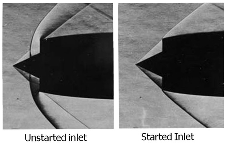
The lines in the image are shock waves. On a simple object like a wedge, the shock angle, wedge angle, and upstream and downstream Mach numbers (Mach number decreases through a shock) are all mathematically tied together. These relations are usually covered in a sophomore or junior level aerodynamics class.
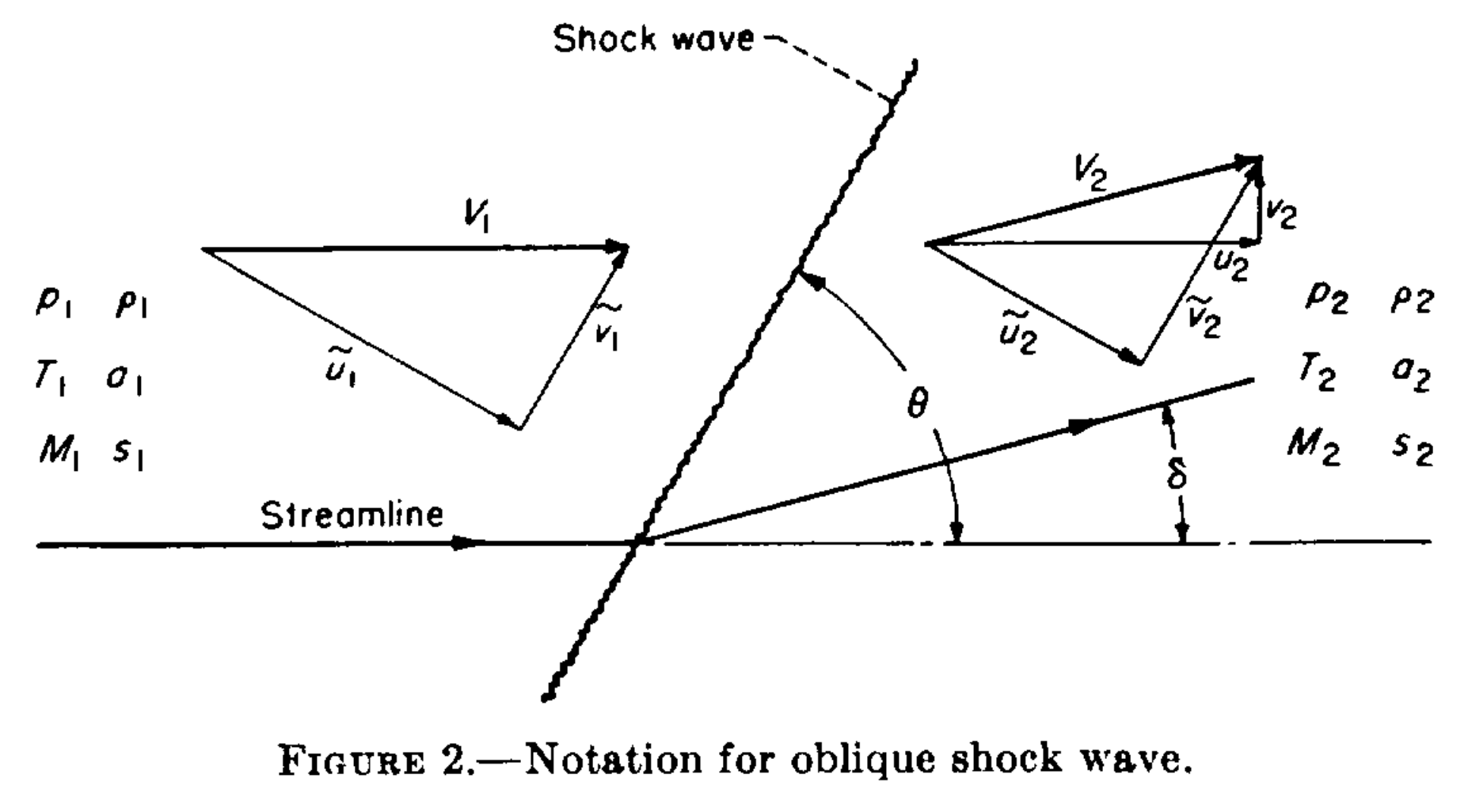
The relation is most concisely summarized in NACA Report 1135. We will adopt its terminology for simplicity. Most importantly, Mach number is $\mathrm{M}$, the wedge angle (also called half angle) is $\delta$, and the shock angle is $\theta$. Let's do a quick example to reinforce these terms.
Warm-up Exercise
Given a wedge half-angle $\delta=10^{\circ}$ and shock angle $\theta=30^{\circ}$, calculate upstream Mach number.
Warm-up Solution
Using Equation 148b on page 622 of the Report, we have
\begin{eqnarray*} \mathrm{M}_1 &=& \sqrt{ \displaystyle\frac{2(\cot{\theta}+\tan{\delta})}{\sin{2\theta}-\tan{\delta}(\gamma + \cos{2\theta})} } \\ &=& \sqrt{ \displaystyle\frac{2(\cot{30^{\circ}}+\tan{10^{\circ}})}{\sin{60^{\circ}}-\tan{10^{\circ}}(1.4 + \cos{60^{\circ}})} } \\ &=& 2.681 \end{eqnarray*}This was easy enough, but of course real life is a little more challenging.
NOTE: from here on out, we are abandoning the subscripts $1$ and $2$ for upstream and downstream, they will now refer to the top and bottom edges of a wedge.
Problem
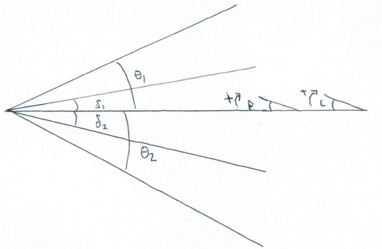
Using upper and lower shock angles and half angles, $\theta_1$, $\delta_1$, $\theta_2$, and $\delta_2$, calculate upstream Mach number. The subscripts $1$ and $2$ refer to the angle measured on the upper and lower wedge. You cannot assume a non-zero pitch $p$ or camera deflection angle $c$, and neither are known quantities (neglect flow angularity in the tunnel).
Down the Wrong Rabbit Hole
You may be first tempted to average the two deflection angles to get the half angle of the wedge. While this is simple and arguably accurate, it is not particularly helpful. There is an offset angle between them that can be caused by two (or more?) things: camera offset angle and the pitch angle of the wedge, $c$ and $p$.
Here's the problem with camera angle and pitch contributions to oblique shocks: changing the camera angle doesn't affect the physics of the shocks, but changing the pitch of the wedge does. Changing $p$ affects the effective half angle for the upper and lower wedges, thus influencing $\theta_1$ and $\theta_2$, but changing $c$ only offsets them. We need an approach that properly incorporates $c$ and $p$.
Solution
It out turns pitch angle is a sort of red herring; the solution lies in ignoring it (explicitly). Pitch is implicitly built into the relationship between the wedge angles. That's not to say it doesn't matter, averaging the wedge angles $\delta_1$ and $\delta_2$, for example, removes the implicit pitch contribution. As long as you don't mess with the half angles, pitch is accounted for.
If it helps, think of the top and bottom as separate wedges. Then we can apply equation 148b with camera angle. By using two equations, one each for top and bottom, we implicitly account for it.
$$\mathrm{M}_{1}^2 = \displaystyle\frac{2[\cot{(\theta_1+c)}+\tan{(\delta_1+c)}]} {\sin{(2\theta_1+2c)}-\tan{(\delta_1+c)}[\gamma + \cos{(2\theta_1+2c)}]} $$ And $$ \mathrm{M}_{2}^2 = \displaystyle\frac{2[\cot{(\theta_2-c)}+\tan{(\delta_2-c)}]} {\sin{(2\theta_2-2c)}-\tan{(\delta_2-c)}[\gamma + \cos{(2\theta_2-2c)}]} $$Subtract the two equations from each other (because $M_{1}=M_{2}$) and we are left with a single equation with the single unknown $c$ (remember, $\delta_1$, $\delta_2$, $\theta_1$ and $\theta_2$ will each be measured).
This is no picnic to solve analytically, but it can be easily tackled with Newton’s method. Newton requires the function and its derivative, which can be calculated using diff in MATLAB or sympy in Python (DON'T DIY). The MATLAB is
function [c,M] = find_offset(t1,t2,d1,d2)
%// returns offset (c) and Mach number

y=1.4;              %// Specific heat ratio
tol=1e-10;          %// Difference required to break loop
maxiterations=1000;
c=0;                %// Initial guess for offset csilon

for i=1:maxiterations
%// 1 corresponds to top edge, 2 corresponds to bottom edge

    M1=2*(cot(t1+c)+tan(d1+c))/(sin(2*(t1+c))-tan(d1+c)*(y+cos(2*(t1+c))));
    M2=2*(cot(t2-c)+tan(d2-c))/(sin(2*(t2-c))-tan(d2-c)*(y+cos(2*(t2-c))));

    dM1=-(2*cot(c+t1)^2-2*tan(c+d1)^2)/...
      (sin(2*c+2*t1)-tan(c+d1)*(cos(2*c+2*t1)+7/5)) ...
      -((2*cot(c+t1)+2*tan(c+d1))*(2*cos(2*c+2*t1)+...
      2*sin(2*c+2*t1)*tan(c+d1)-(tan(c+d1)^2+1)*(cos(2*c+2*t1)+7/5)))...
      /(sin(2*c+2*t1)-tan(c+d1)*(cos(2*c+2*t1)+7/5))^2;

    dM2=(2*cot(t2-c)^2-2*tan(d2-c)^2)...
      /(sin(2*t2-2*c)-tan(d2-c)*(cos(2*t2-2*c)+7/5))+...
      ((2*cot(t2-c)+2*tan(d2-c))*(2*cos(2*t2-2*c)+...
      2*sin(2*t2-2*c)*tan(d2-c)-(cos(2*t2-2*c)+7/5)*(tan(d2-c)^2+1)))...
      /(sin(2*t2-2*c)-tan(d2-c)*(cos(2*t2-2*c)+7/5))^2;

    %// Newtons Method
    Mdiff=M1-M2;
    dMdiff=dM1-dM2;
    diff=Mdiff/dMdiff;
    c=c-diff;

    %// Check for early break
    if abs(diff) < tol
      break
    end

end %// for loop
end %// function
If you're a skeptic, the alarm bells might be ringing. You can't just ignore what components factor into the offset angle...can you?
This is hard to prove (frankly I'm not sure how one would rigorously), and even a rigorous mathematical proof is probably not very exciting The below test cases make a good case for the algorithm's veracity. Here $\delta$ is the "original" half angle of the wedge; it is not used except to help generate test cases.
| $\mathrm{M}$ | $\delta$ | $p$ | $c$ | $\delta_1=(\delta+p)-c$ | $\delta_2=(\delta-p)+c$ | $\theta_1=\theta(\mathrm{M},\delta+p)-c$ | $\theta_2=\theta(\mathrm{M},\delta-p)+c$ |
|---|---|---|---|---|---|---|---|
| $2$ | $10^{\circ}$ | $0^{\circ}$ | $0^{\circ}$ | $10^{\circ}$ | $10^{\circ}$ | $\theta_{10}-0^{\circ}=39.31^{\circ}$ | $\theta_{10}+0^{\circ}=39.31^{\circ}$ |
| $2$ | $10^{\circ}$ | $5^{\circ}$ | $5^{\circ}$ | $10^{\circ}$ | $10^{\circ}$ | $\theta_{15}-5^{\circ}=40.34^{\circ}$ | $\theta_{5}+5^{\circ}=39.30^{\circ}$ |
| $2$ | $10^{\circ}$ | $5^{\circ}$ | $0^{\circ}$ | $15^{\circ}$ | $5^{\circ}$ | $\theta_{15}-0^{\circ}=45.34^{\circ}$ | $\theta_{5}+0^{\circ}=34.30^{\circ}$ |
| $2$ | $10^{\circ}$ | $0^{\circ}$ | $5^{\circ}$ | $5^{\circ}$ | $15^{\circ}$ | $\theta_{10}-5^{\circ}=34.31^{\circ}$ | $\theta_{10}+5^{\circ}=44.31^{\circ}$ |
| $2$ | $10^{\circ}$ | $5^{\circ}$ | $-5^{\circ}$ | $20^{\circ}$ | $0^{\circ}$ | $\theta_{15}+5^{\circ}=50.34^{\circ}$ | $\theta_{5}-5^{\circ}=29.30^{\circ}$ |
| $2$ | $10^{\circ}$ | $-5^{\circ}$ | $5^{\circ}$ | $0^{\circ}$ | $20^{\circ}$ | $\theta_{5}-5^{\circ}=29.30^{\circ}$ | $\theta_{15}+5^{\circ}=50.34^{\circ}$ |
| $2$ | $15^{\circ}$ | $-5^{\circ}$ | $5^{\circ}$ | $5^{\circ}$ | $25^{\circ}$ | $\theta_{10}-5^{\circ}=34.31^{\circ}$ | $\theta_{20}+5^{\circ}=58.42^{\circ}$ |
Here, $\theta(\mathrm{M},\delta)$ denotes a function to calculate shock angle from Mach number and wedge angle. This can be accomplished with equation 150a (the solution of which was the motivation for the previous post). The four test shock angle values are $\theta_{5}=34.30^{\circ}$, $\theta_{10}=39.31^{\circ}$, $\theta_{15}=45.34^{\circ}$, $\theta_{20}=53.42^{\circ}$.
If you write your own tests, stay away from negative and non-physical angles. Furthermore, negative angles are properly handled with Prandtl-Meyer expansion, which uses a different set of assumptions and equations.
I ran them through the code (I encourage you to do the same) and they all spit out the same Mach number, despite having either the same offset angle from different sources, or different offset angles.
If you want to run the code yourself, you can download it here. NOTE: the angles in this code are all in degrees (contrary to the snippet above).
Other Considerations
Earlier we neglected tunnel angularity. This was essential to keep our problem constrained. Solving for (one component) tunnel angularity can be achieved if we know the camera offset angle or pitch angle, but not if we know neither (and no other information). It is not a perfect substitution, but it is a simple enough exercise (and will of course be left to the reader). Depending on your setup, you may trust you camera angle more than your tunnel angularity.